How to Make a Real-Time Operating System
July 3, 2026
A technical guide that details how to implement a RTOS for the STM32F4 Cortex-M family!
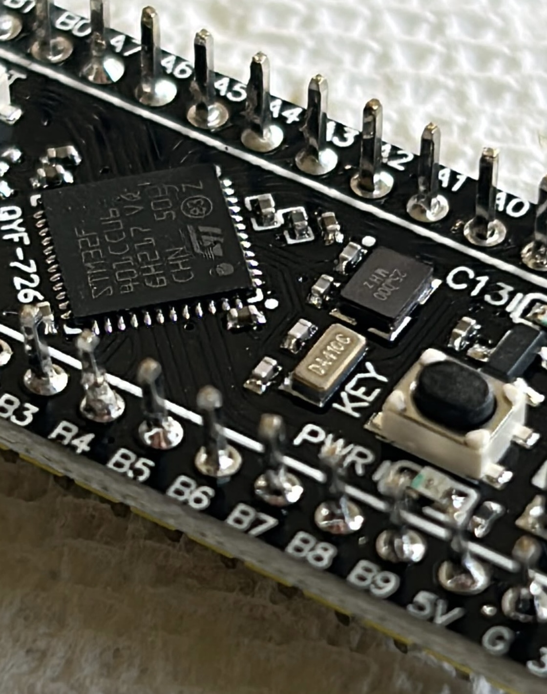
Firefly is a bare-metal real-time operating system I wrote for the STM32F401CCU6 microcontroller. I implemented everything from scratch, from the linker script to the HAL to the queue & mutex data structures, with only the CMSIS register files as my foundation.
What is a Operating System?
An operating system is a piece of code that lives between the hardware and application space.
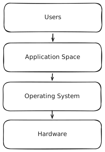
Abstraction of OS levels
In a regular windows computer, the OS manages the hardware and resources, providing an inteface to network, disk, and CPU. For example, it provides the ability for a filesystem program to create and manage different files.
What is a Real Time OS then?
A real-time operating system is a low level implementation of the above specifications. It provides the guarantee that a specific event at a moment in time will be handled deterministically.
In other words, it allows me to handle data in time constrained environments and control the current executing task!
Why do I need an RTOS?
This summer, I am building an autonomous drone! Instead of paying $90 for a flight controller, I am using an STM32 alongside custom, hand-made flight software to fly the drone.

My 3D printed Autonomous Drone Frame
With this comes the need to have logic that individually controls the drones 4 motors and to update them quickly. But my STM32 only has one processor, meaning it can only execute one instruction at a time. Unlike a regular computer, it cannot execute multiple instructions at the same time.
So the trick is to make the one processor look like it does. It achieves this by saving the "context" of the task (all the current values in the registers) into memory before quickly switching to another task, loading its context before continuing on.
This architecture enables me to write motor logic without concern for context switching, ensuring application level logic is isolated!
File Structure
Disclaimer: I had help from Claude in generating a professional file structure. I don't know what I don't know sometimes and I find that AI is helpful in finding a direction, but I DID NOT use it to generate code in this project.
build
cmake
stm32_toolchain.cmake
config
rtos_config.h
docs
examples
blinky
rtos_demo
CMakeLists.txt
include
rtos.h
src
hal
kernel
linker
port
startup
tests
integration
unit
tools
flash.sh
setup.sh
CMakeLists.txt
LICENSE
README.md
Here, CMakeLists.txt at the root servers as our guidelines for the entire build configuration and is what allows us to compile code on an x86 laptop for an ARM based microcontroller.
The rest of the files are fairly self explanatory.
References
You will need all five of these docs:
Primer: The Compilation process
Before we write a RTOS, we need to blink the light on the microcontroller to demonstrate we have control. And before we can blink the light, we need to be able to compile source code from out laptop to a binary file compatible with our STM32.
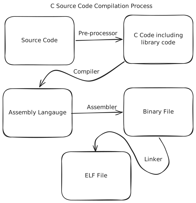
GCC compilation process
The C programming language is genuinely a magical language, and its compilation process through the GCC compiler collection is equally as elegant and magical.
First, GCC takes a source file like main.c as input. C files import libraries through "include" statements. For example, consider this source file:
#include <stdlib.h>

void main(void) {

    /*  malloc is used to allocate bytes of memory!
        Here we are allocating 16 bytes */

    int *pointer_to_memory = malloc(16);

    /* Do smth with memory, for example, store stuff */

    *pointer_to_memory = 5;

    /*  We need to let the computer know
        we are done with the memory */

    free(pointer_to_memory);
}
The library stdlib allows us to use malloc. Now, GCC compilation will take this C file and produce:
/*  Replace #include ... with a
    ton of declarations ... */

/* Eventually malloc & free are declared: */

extern void *malloc (size_t __size) __attribute__ ((__nothrow__ , __leaf__)) __attribute__ ((__malloc__))
     __attribute__ ((__alloc_size__ (1))) ;

extern void free (void *__ptr) __attribute__ ((__nothrow__ , __leaf__));

/* Normal program, comments removed */

void main(void) {
    int *pointer_to_memory = malloc(16);
    *pointer_to_memory = 5;
    free(pointer_to_memory);
}
Now GCC will compile from C into assembly. Fun fact, compilation is done in one pass, which is why in C you must declare a function exists before you use it!
	.file	"main.c"
	.text
	.globl	main
	.type	main, @function
main:
.LFB6:
	.cfi_startproc
	pushq	%rbp
	.cfi_def_cfa_offset 16
	.cfi_offset 6, -16
	movq	%rsp, %rbp
	.cfi_def_cfa_register 6
	subq	$16, %rsp
	movl	$16, %edi
	call	malloc@PLT
	movq	%rax, -8(%rbp)
	movq	-8(%rbp), %rax
	movl	$5, (%rax)
	movq	-8(%rbp), %rax
	movq	%rax, %rdi
	call	free@PLT
	nop
	leave
	.cfi_def_cfa 7, 8
	ret
	.cfi_endproc
.LFE6:
	.size	main, .-main
	.ident	"GCC: (GNU) 16.1.1 20260430"
	.section	.note.GNU-stack,"",@progbits
I will save explaining this assembly for another time. For now, just know that assembly instructions are the lowest level computer instructions that exist. The assembler maps each instruction to a sequence of 1s and 0s, eventually producing an Object file.
This Object (binary) file still contains undefined references. In this case, "call malloc@PLT" is still calling a function that, at least as far as it can see, does not exist yet.
So finally, the linker comes through and resolves these undefined references, pulling from static libraries these definitions and replacing them.
The result is an ELF (for windows an exe) file. This is not human readable:
ELF>P@�6@8@@@@H���pp��   ���-�=�=PX�-�=�=����$$0!0!0!@p!p!p!  S�td0!0!0!@P�td
$$T�td� � � �Q�tdR�td�-�O k z
"freemalloc__libc_start_main__cxa_finalizelibc.so.6GLIBC_2.34GLIBC_
2.2.5_ITM_deregisterTMCloneTable__gmon_start___ITM_registerTMCloneTable.���8ui
C�@��@�?�?�?�?�?@��H�H��/H��t��H���5�/�%�/@�%�/h������%�/h��
�����1�I��^H��H���PTE1�1�H�=��K/�f.�H�=�/H��/H9�tH�./H��t
�����H�=i/H�5b/H)�H��H��?H��H�H��tH�H�=/��.�c�����.]�f.��@ff.����g�
��UH��H��������H�E�H�E��H�E�H�����������H�H�� ���TL���<E���|zRx
                                        ���&D$4����0FJ
j �?;*3$"\����/A�C
��� 0\�������
\������� l�������&


               0GNU����GNU@�.
x�����o���
�
 �?0@�  ������oP���o���o<���o�=6F@GCC: (GNU) 16.1.1 20260430��      p! ��
                     �!
                       �4
                         �J @V�=}
                                 @��=�������� ����=� ��?�
xP@] l@y ��(@V
              P&� @�
                    I/� @� �"�
Scrt1.o__abi_tagcrtbeginS.oderegister_tm_clones_
_do_global_dtors_auxcompleted.0__do_global_dtors_aux_fini_
array_entryframe_dummy__frame_dummy_init_array_entrymain.
ccrtendS.o__FRAME_END___DYNAMIC__GNU_EH_FRAME_HDR_GLOBAL
_OFFSET_TABLE_free@GLIBC_2.2.5__libc_start_main@GLIBC_2.34_ITM_
deregisterTMCloneTable_edata_fini__data_start__gmon_start__
__dso_handle_IO_stdin_usedmalloc@GLIBC_2.2.5_end__bss_startmain_
_TMC_END___ITM_registerTMCloneTable__cxa_finalize@GLIBC_2.2.5_init
.symtab.strtab.shstrtab.note.gnu.build-id.interp.gnu.hash.dynsym.
dynstr.gnu.version.gnu.version_r.rela.dyn.rela.plt.init.text.fini.
rodata.eh_frame_hdr.eh_frame.sframe.note.gnu.property.note.ABI-tag.
init_array.fini_array.dynamic.got.got.plt.data.bss.comment�$.��6���o�@
�  �  $�( ( ����o� � �0!0!�p!p! ������=�-��?��?�/(
 @ 0 00x�3��5
This file can now be executed on the target system!
Intro: The Linker File
Now that you understand the compilation process, its time to go deeper. Remember that linker phase in the compilation process? Well the linker can't do its job if it doesn't know the layout of memory. The linker needs to know where you want to place addresses, how large the stack should be, and how your code should be organized in memory.
This means, before we can get to writing this linker file, we need to know about...
Primer: Basic ELF Memory Map
ELF (Executable and Link Format) is GCC/UNIX specific, with Windows having a similar but different memory layout.
Please take this with many, many grains of salt, but in general, the memory layout or memory map looks like this:
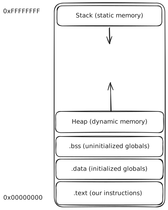
ELF Memory Map
.text, .bss, & .data all tend to be near the start of memory (0x00000000) in memory maps. The stack, which is used for static memory allocations, usually lives near the very end of memory (0xFFFFFFFF). The stack grows downwards!
So each time you do a:
int some_variable = 5;
in C, you are assigning a memory location in the stack memory space to 5. some_variable just represents that memory address where 5 lives.
In contrast, the heap grows upward. So every dynamic memory allocation like:
int *pointer = malloc(16);
is just adding 16 bytes for you to use in the heap memory space!
For exact, detailed information, this is a great resource! But only if you are curious! It is only necessary to have a general idea of memory to continue!
Back to Linker File
We will be writing our linker file in a file called 'stm32f401.ld' under src/linker! Let's start with the first requirement: defining memory addresses!
For this, you need two things:
-
A handy 900 page technical doc. called the reference manual! You can find the stm32f401xB/C/D/E doc here
-
You now need to navigate & find the Memory mapping table, here page 42 of the reference manual.
Microcontrollers have designated sections of memory for your use. We have two sections who addresses we are concerned with: sram & flash.
Flash is a region of memory which allows the persistance of instructions even when power is off. It works by trapping electrons in tiny, microscopic cells! When we eventually 'flash' our code to the STM32, we will actually be overwritting this memory section.
sram is a region of memory that is volatile. That is, sram uses power to actively hold data. Why might we use it over non-volatile memory such as flash? It's fast. Incredibly fast!
So, using our docs, lets tell the linker at what memory address & what length these memory sections exist at!
MEMORY
{
    flash (RX) : ORIGIN = 0x08000000, LENGTH = 64K
    sram  (RW) : ORIGIN = 0x20000000, LENGTH = 64K
}
We also need to configure permissions! Flash should not be something that code normally overwrites. There are several reasons, but one of them is that hardware does not have the ability to reset just one byte in flash. Instead, because flash memory actually is naturally 1s instead of 0s on reset, flash must be reset in entire sections at a time. So, lets just give flash the ability to be read and pulled in for execution.
SRAM, on the other hand, is volatile memory and can be read & written at any time! SRAM is not execute for several reasons. The first is reliability. If an error happens and the stack is corrupted, ensuring that garabage cannot be executed is critical. The other is security. In this project, instructions live in flash while data lives in sram. There is no need for sram to ever be able to execute anything!
Linker: SECTIONS
Before we get to that, we can define some information.
ENTRY(Reset_Handler)
This tells the linker that the Reset Handler function will be the place where instructions are executed. However, on Cortex M architecture, the harware will always read 0x00000000 first and we are going to be placing Reset Handler there anyway.
However, it does provide some benefit. The linker will try to remove unreferenced variables. Because Reset Handler lives at 0x00000000 and won't be called by anything, the linker will try to remove it. By defining the entry point, we can avoid that.
Next, we need to configure the size of our stack:
_min_stack_size = 0x800
In this case, I choose 2K bytes.
Now the good stuff:
SECTIONS
{
    .isr_vector : ALIGN(4)
    {
        _vector_start = .;
        KEEP(*(.isr_vector))
        . = ALIGN(4);
        _vector_end = .;
    } > flash

    .text : ALIGN(4)
    {
        _text_start = .;
        *(.text)
        *(.text*)
        _text_ro_start = .;
        *(.rodata)
        *(.rodata*)
        . = ALIGN(4);
        _text_end = .;
    } > flash

    .data : ALIGN(4)
    {
        _data_start = .;
        *(.data)
        *(.data*)
        . = ALIGN(4);
        _data_end = .;
    } > sram AT > flash

    _data_flash_start = LOADADDR(.data);

    .bss : ALIGN(4)
    {
        _bss_start = .;
        *(.bss)
        *(.bss*)
        *(COMMON)
        . = ALIGN(4);
        _bss_end = .;
    } > sram

    end = .;

    ._stack : ALIGN(8)
    {
        _stack_start = .;
        . = . + _min_stack_size;
        . = ALIGN(8);
        _stack_top = .;
    } > sram
}
SECTIONS is where we define the layout of flash memory itself. It is here where we tell the linker what data belongs where.
Vector Table
According to the Programming Manual for the Cortex M4, on page 40, section 2.3.4, the architecture expects the vector table to live at 0x00000000 (which in the context of flash, is 0x08000000).
.isr_vector : ALIGN(4)
{

} > flash
So we will define .isr_vector (our vector table function we will define later). In the linker script, we need to tell the script what memory to use, which in this case should be flash.
Syntax
In linker file, . is used to specify the current address we exist at. For our convenience and ease of use later, we will define the start and end addresses of each section.
_vector_start = .;
...
_vector_end = .;
KEEP is again used to ensure that the isr_vector section is not taken out by the linker. In the meantime, the syntax:
*(.isr_vector)
This means that from every object file, extract the .isr_vector and place them there in memory. If we wanted more fine grained control, we could specify an object file:
task.o(.isr_vector)
This will extract the .isr_vector from the task object file.
Alignment
We then ensure the end address is on a multiple of 4:
. = ALIGN(4);
Next, we will worry about the .text section. Here, I have placed .rodata inside the .text section, but it could have just as easily been placed outside in its own thing. .rodata is used to hold read-only data, such as constant globals and string literals.
Last few things to note, on page 231, section 4.4.7 of the Reference Manual, we have the Configuration and Control Register. Here, it is shown that the reset value defaults to 0x00000200, which is 512 in decimal value. Take the log:
log2(512) = 9
Thus, the default value is therefore to have 9-th bit set, which according to the docs, means that the stack defaults to 8 byte aligned.
When we define the stack, we must ensure that it cooperates!
Defensive Coding for Legacy requirements
Note, that in .bss, I included *(COMMON). I won't dive too much into it, but basically COMMON is a legacy section that compilers don't generate anymore but is included as defensive coding!
SRAM & Flash to the Linker
_data_flash_start = LOADADDR(.data);
The above defintion is absolutely necessary! Previously, we defined things like _data_start and _data_end. Note the . tracks the current addresses on whichever section we specify.
So when we specified that data should be written to flash with "> flash", then the period represents flash memory addresses and vice versa.
Because we can only flash to flash memory, later in startup script, we will manually copy the data and bss sections into sram. Therefore, the . represents sram addresses but we need to know where in flash .data begins. So we use LOADADDR as a way to store the location in flash of the beginning of .data for the copy.
Special handling of .data placement
Notice that _stack and _bss use "> sram" while .data does "> sram AT > flash".
Why is that?
Well, this is because .data is special! .bss holds uninitialized global variables, meaning that they are all zeroed out. _stack also contains no values yet, it is just reserving space right now for the stack.
.data is different, because we have values that need to be assigned. The data section holds initialized globals. So, we need to do two things. We need to tell the linker we are storing the values in flash: "AT > flash". And we need to tell the linker that we are going to be using them in sram: "> sram".
Note the syntax is exactly:
> VMA AT > LMA
Where VMA is virtual memory address and LMA is the moad memory addresses. It will not work if you do:
AT > flash > sram
This conclues what you need to know for the linker script!
Startup Script
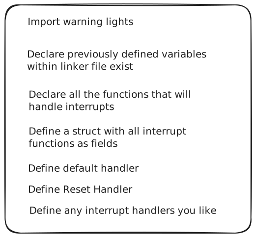
Overview of Startup
We will write write the warning lights logic in a second. For now, lets begin writing our Startup script.
Remember the variable definitions we previously defined like "_vector_start" and "_text_start"? Well we will now declare ensure that startup is aware of their existence:
extern uint32_t _stack_start;
extern uint32_t _stack_top;
extern uint32_t _data_start;
...
Now, refer to Table38: Vector Table on page 203, of the Reference Manual! This is what the hardware demands must exist at these addresses. The vector table will live at the 0x00000000 (within the context of flash, so really at 0x08000000) and will be the first thing the processor executes on startup.
We need to make a handler function for every non-reserved interrupt. So for example:
void NMI_Handler(void)          __attribute__((weak));
void HardFault_Handler(void)    __attribute__((weak));
...
void WWDG_IRQHandler(void)      __attribute__((weak, alias("Default_Handler")));
...
The "__attribute__((weak))" is not C syntax but special GCC syntax. It allows a function definition to be overwritten if it is defined elsewhere. Functions coupled with 'weak' + 'alias("Default_Handler")', attributes can be both overwritten and default to Default_Handler if they are not defined otherwise.
There are 11 system exceptions and an innumerable number of pheripheral interrupts. Two of the system exceptions: default and reset handler, should not be able to be overwritten. The other 9 can be if so desired.
The remaining pheripheral interrupts should default to Default Handler. This is because, unlike a regular computer, interrupts and exceptions should not be unexpected. Therefore, if an interrupt occurs which should not, we default to just an infinite blinking warning light.
Then define your struct:
__attribute__ ((section(".isr_vector")))
void (* const vector_table[])(void) = {
    ((void (*)(void)) (&_stack_top)),
    Reset_Handler,
    NMI_Handler,
    HardFault_Handler,
    MemManage_Handler,
    ...
The first memory location must be the top of the stack while the second must be the reset handler. Follow the rest of the documentation for the rest.
Define the interrupts where you want things to occur and plan to use. For reset Handler:
void Reset_Handler(void) {
    uint32_t *ptr_data_sram = &_data_start;
    uint32_t *ptr_data_flash = &_data_flash_start;
    uint32_t data_size_words = &_data_end - &_data_start;

    for (uint32_t i = 0; i < data_size_words; i++) {
        *ptr_data_sram++ = *ptr_data_flash++;
    }

    uint32_t bss_size_words = &_bss_end - &_bss_start;
    uint32_t *ptr_bss = &_bss_start;

    for (uint32_t i = 0; i < bss_size_words; i++) {
        *ptr_bss++ = 0;
    }

    main();

    warning_light_init();
}
This is the heart of the startup script. Here, we need to do two things:
-
Copy data from flash into sram
-
Zero out BSS
We then pass control to main function!
Main Function
The main function will live under "examples" folder and will control the flow of our program. So far, we have setup the ability to compile to our architecture and what should happen during the initialization of the microcontroller.
Now we move onto configuring & customizing the microcontroller!
#include "hal.h"
#include "stdint.h"
#include "fault_indicator.h"

int main(void) {
    fpu_init();
    rcc_init();
    rcc_enable_gpioc();
    gpio_init_pc13();
    nvic_init();

    while (1) {
        gpio_toggle_pc13();
        delay(10000000);
    }

    return 0;
}
Lets go over whats going on here. First we need to configure the stm32. We do that with 5 functions. We need to turn on the fpu, configure the clock with the Reset & Control register, enable the gpio pin mapped to the map, and configure the priority of interrupts.
After that, we will loop forever, toggling the LED.
FPU enable
Following this resource, we are able to turn on the FPU bits with:
void fpu_init(void) {
    SCB->CPACR |= ((3U << 20U) | (3U << 22U));
}
GPIO
Using this reference, we find that under USER LED section, the LED is connected to PC13.
Now go to page 158 of the reference manual, here we need to set the mode register for PC13 to General Purpose Output mode. This means bit 26 needs to be set to 1. We also need to clear bit 27:
void gpio_init_pc13(void) {
    RCC->AHB1ENR |= RCC_AHB1ENR_GPIOCEN;

    GPIOC->MODER &= ~(3U << 26);

    uint32_t enable_output_mode = 1U << 26;
    GPIOC->MODER |= enable_output_mode;
}
We also need to turn on the clock for the GPIO port before we configure it.
Finally, we would like to turn the light on and off again. Lets go to the output data register (ODR), and repeatedly set on and off the 13th bit.
/*
    Turn on LED
*/
void gpio_set_pc13(void) {
    GPIOC->ODR &= ~(1U << 13);
}

/*
    Turn off LED
*/
void gpio_clear_pc13(void) {
    GPIOC->ODR |= (1U << 13);
}

/*
    Toggle LED
*/
void gpio_toggle_pc13(void) {
    GPIOC->ODR ^= (1U << 13);
}
Reset and Control Register
Page 104 of Reference Manual
Now we will configure the clock. There are several potential sources available to us: HSI and HSE.
High Speed External is an option but requires, like in the name, an external crystal oscillator. While it does provide higher precision and excellent stability but for our drone, High Speed Internal at 84 MHz is good enough!
Enable it:
RCC->CR |= RCC_CR_HSION;
Page 104, we now need to wait for HSI to be stable:
while(!(RCC->CR & RCC_CR_HSIRDY));
Now we need to select HSI for PLL to lock on, reset PLL (Phase-Locked Loop), and turn on max clock speed: 84 MHz. We will transition from HSI clock to PLL because PLL allows us to surpass the normal 16 MHz HSI is stuck at. We first had to turn on HSI though!
/* Select HSI clock */
RCC->PLLCFGR &= ~(RCC_PLLCFGR_PLLSRC);

/* Reset PLL CFGR*/
RCC->PLLCFGR &= ~(RCC_PLLCFGR_PLLM
   | RCC_PLLCFGR_PLLN
   | RCC_PLLCFGR_PLLP
);

/* Configure the PLL to be 84MHz */
RCC->PLLCFGR |= (16U << RCC_PLLCFGR_PLLM_Pos);
RCC->PLLCFGR |= (336U << RCC_PLLCFGR_PLLN_Pos);
RCC->PLLCFGR |= (1U << RCC_PLLCFGR_PLLP_Pos);
Note that we are zero-ing out PLL CFGR so that previous garabage values don't interfere.
Now using the docs on Page 105, we have two equations:
-
f(VCO clock) = f(PLL clock input) * (PLLN / PLLM)
-
f(PLL general clock output) = f(VCO clock) / PLLP
It is known that the fastest the stm32 can go is 84 MHz. We also have a few restrictions, with PLLP needs to be 2, 4, 6, or 8, PLLN needing to be greater than to 191 or less than 433, and finally PLLM needing to be between 2 and 63 inclusive.
Lets do some reverse engineering:
Start by setting to PLLP to 4, that seems reasonable:
84 = VCO clock / 4 336 = VCO clock PLL Clock Input = 16 MHz 336 = 16 * (PLLN / PLLM) PLLM = 16 PLLN = 336
Perfect! Now PLL is configured and ready but nothing is using it yet. This leads us to:
/* Zero out AHB so system clock not divided*/
RCC->CFGR &= ~(RCC_CFGR_HPRE);

/* Reset APB1 */
RCC->CFGR &= ~(RCC_CFGR_PPRE1);

/*  APB1 cannot exceed 42 MHz, since
    we are running at 84, divide by 2 */
RCC->CFGR |= (4U << RCC_CFGR_PPRE1_Pos);

/*  Reset APB2 & keep zeroed bc. APB2 can
    handle 84MHz */
RCC->CFGR &= ~(RCC_CFGR_PPRE2);
As you will have gathered from the comments, we are now configuring the Reset & Control Register. Follow page 107 of the reference, you will find that we have several options of bits to configure.
First and foremost, while already set at this point, we will explicitly declare the AHB to be running at its normal 84 MHz speed. HPRE is the AHB prescaler. AHB is out fast data bus where the CPU itself lives on. It will be needed for later projects the RTOS is used on.
APB1 & APB2 are slower data busses for peripherals that don't need to run at full speed. And as such we will set their prescalers (PPRE1) to a reduced rate of 42 MHz (its max according to the docs) while keeping PPRE2 at its normal 84 MHz rate.
/* Reset wait states*/
FLASH->ACR &= ~(FLASH_ACR_LATENCY_Msk);

/* 2 wait states for flash at 3.3V & 84 MHz*/
FLASH->ACR |= (2U << FLASH_ACR_LATENCY_Pos);
Page 46 of Reference Manual. Now that we are using PLL with a different clock frequency than 16 MHz, the hardware will not be able to read flash memory without additional configuration. We need to intentionally slow down to read flash memory, by introducing latency!
With a voltage range of 3.3V and 84 MHz clock frequency, the docs recommend we use 2 waiting states. To do this, we need to configure the ACR register as seen above!
Note, it is essential that we configure flash wait states before we turn on PLL. Otherwise, we will get corrupted states.
Turn on PLL and wait for hardware to lock it:
RCC->CR |= RCC_CR_PLLON;
while(!(RCC->CR & RCC_CR_PLLRDY));
Finally, we need to set SysClock as PLL:
/* Reset CFGR*/
RCC->CFGR &= ~(RCC_CFGR_SW_Msk);

/* Select PLL as Sys clock*/
RCC->CFGR |= (2U << RCC_CFGR_SW_Pos);

/* Wait for System Clock Switch*/
while((RCC->CFGR & RCC_CFGR_SWS_Msk) != (2U << RCC_CFGR_SWS_Pos));
NVIC
void nvic_init(void) {
    NVIC_SetPriority(PendSV_IRQn, 0xFF);
    NVIC_SetPriority(SysTick_IRQn, 0x00);
}
For the Nested Vector Interrupt Control register, we will set the two priority interrupts. Note that the lower numbered interrupts have a higher priority. Here, we are setting System Tick interrupt to the highest priority while PendSV (which will be used for context switching) to the lowest priority.
Why do we set context switching to the lowest priority? Well, for that, you need to understand the PendSV interrupt:
PendSV Interrupt
Pending Supervisor Call is a software controlled exception. It is intended for context switching. It is desgined to never delay time critical tasks driven by SysTick or peripheral interrupts. It fires when the processor returns to thread mode.
SysTick decides when a task should run but it does not perform the context switch. This would make SysTick too long and unstable to perform is normal necessary time critical operations.
On PendSV execution, Cortex M hardware will automatically push the stack frame onto the currently executing stack (MSP or PSP). This frame consists of:
- R0 - R3
- R12
- LR
- PC
- xPSR
You are then responsible for saving any additional registers manually. It will automatically restore this frame of a task it switches too.
This explains why PendSV must be the lowest priority, because if it wasn't, then a hardware interrupt could be overwritten by PendSV.
Think about what is happening here. In a hardware interrupt mode, we are in handler mode and MSP represents the current session. PSP is frozen in the last executing task, meaning that if PendSV fires while we are in handler mode, then we will be losing the state of the interrupt registers.
To conclude main, we will then setup tasks:
task_create(&task_one, 1, "task one");
task_create(&task_two, 2, "task two");

scheduler_start();

return 0;
For now, because we have not written the kernel yet, just do a simple blinking light:
while(1) {
    gpio_toggle_pc13();
    delay(10000000);
}

return 0;
Port
So far I have covered how to setup the hardware abstraction layer, linker script, main function, Reset Handler, and startup code.
Now we have two remaining tasks: the kernel and the port layer. I have intentionally separated the layers of code to increase portability.
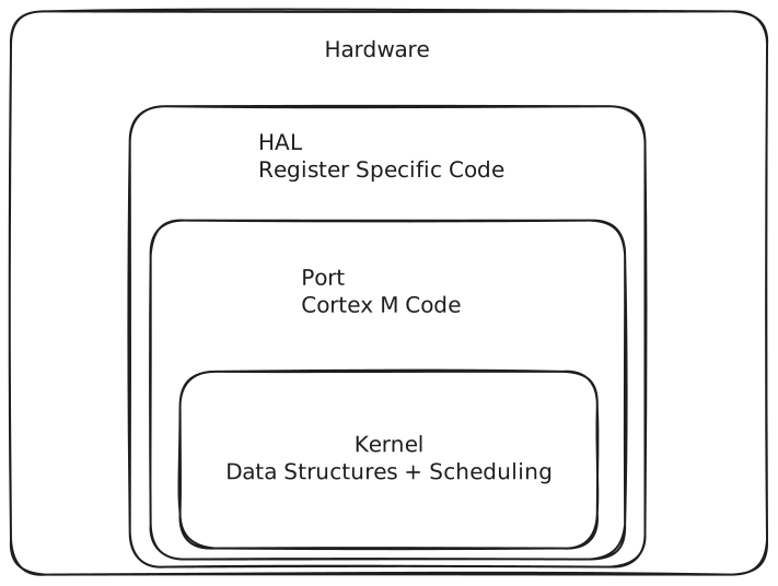
Abstraction Layers
The HAL directly communicates with hardware registers, the port folder represents Cortex-M specifics while kernel is our high level scheduling and data structure code.
Lets setup our task code. We will be using custom 'Task' data types throughout our code in both Kernel & Port, so I created a separate root level folder to hold this shared logic.
First, I defined the maximum number of tasks and the bytes each task should get. For right now, these were complete arbitrary, I just needed enough:
#define MAX_TASKS 16
#define TASK_STACK_SIZE 256
Next, I defined my Task State type:
typedef enum {
    UNINITIALIZED,
    READY,
    RUNNING,
    BLOCKED
} Task_State;
Simple enough. We also need Task type itself:
typedef struct {
    uint32_t *stack_ptr;
    uint32_t *stack_base;
    uint32_t stack_size;
    uint32_t delay_until;
    Task_State state;
    uint8_t priority;
    const char *name;
} Task;
Several things here, we need to store metadata on each Task we will work with.